• There were many reasons for the change of the site software, the biggest was security. The age of the old software also meant no server updates for certain programs. There are many benefits to the new software, one of the biggest is the mobile functionality. Ill fix up some stuff in the coming days, we'll also try to get some of the old addons back or the data imported back into the site like the garage. To create a thread or to reply with a post is basically the same as it was in the prior software. The default style of the site is light colored, but i temporarily added a darker colored style, to change you can find a link at the bottom of the site.

Can anyone with a Big Blue Lift provide advice on my lifting issues?

From the pics in your posts # 37 & 38, you might need to re-think using the 18cm mark that you're lining the left edge of that channel up with in post #29, and move it whichever way/however far it needs to let the BB' s rear shock lifting saddle line up under the rear shock itself, and leave more room for the brake pedal etc. on the other side of BB's vertical main lifting spar... :unsure:

Quite possibly, it'd all be a lot easier for you if you used a bit of solvent to wipe off ALL the blue marks on BB and then, instead of trying to 'force-match' the BB Brackets to those marks and the appropriate points on the underside of your Spyder, you left all the nuts/U-bolts etc. on the BB channels & bracketry etc. juuust a little loose until you've actually matched the lifting points with the underside of your Spyder; and then once everything aligns and you're lifting in the right spots (regardless of wherever some instructions or blue marks on the BB or whatever/whoever might suggest the brackets should be, but which don't match up to where you think they're meant to go), and only then, once you have BB's lifting points aligned under the appropriate hard points on the Spyder, should you tighten up all the nuts, channels, U-bolts, & brackets etc. and complete the lift?! :rolleyes:

AFAICS, the 3rd & 4th pics in post #38 AND at least the 2nd pic in post #37 show that you've got that lift channel secured onto the BB lift arm at least about 20mm too far to the right, so you need to shorten the reach of that channel by at least that 20mm, maybe a bit more if you don't want the brake pedal pushing up hard against the right side of BB's main vertical spar, or the foot peg U-clamp to be trying to doing dodgy things too?! 🤨
 
This is the pre-2020 RT. It doesn't use the floorboard mounting bolt holes like the 2020 and later. Is that what you mean?
Yep.

From the pics in your posts # 37 & 38, you might need to re-think using the 18cm mark that you're lining the left edge of that channel up with in post #29, and move it whichever way/however far it needs to let the BB' s rear shock lifting saddle line up under the rear shock itself, and leave more room for the brake pedal etc. on the other side of BB's vertical main lifting spar... :unsure:

Quite possibly, it'd all be a lot easier for you if you used a bit of solvent to wipe off ALL the blue marks on BB and then, instead of trying to 'force-match' the BB Brackets to those marks and the appropriate points on the underside of your Spyder, you left all the nuts/U-bolts etc. on the BB channels & bracketry etc. juuust a little loose until you've actually matched the lifting points with the underside of your Spyder; and then once everything aligns and you're lifting in the right spots (regardless of wherever some instructions or blue marks on the BB or whatever/whoever might suggest the brackets should be, but which don't match up to where you think they're meant to go), and only then, once you have BB's lifting points aligned under the appropriate hard points on the Spyder, should you tighten up all the nuts, channels, U-bolts, & brackets etc. and complete the lift?! :rolleyes:

AFAICS, the 3rd & 4th pics in post #38 AND at least the 2nd pic in post #37 show that you've got that lift channel secured onto the BB lift arm at least about 20mm too far to the right, so you need to shorten the reach of that channel by at least that 20mm, maybe a bit more if you don't want the brake pedal pushing up hard against the right side of BB's main vertical spar, or the foot peg U-clamp to be trying to doing dodgy things too?! 🤨

That’s what I did. Seems counterintuitive to what the instructions say, but it's actually a cleaner method to fit/match up with all the crucial points according to what you’re actually dealing with. But the measurements from the guide are a good place to start.
 
Just for grins, I asked Google how to set up to lift an RT on Big Blue. This is what came back;

To set up and lift a 2014 Can-Am Spyder RT using a Big Blue Eazy-Rizer lift, follow these steps for a secure, 3-point stable lift:

1. Initial Prep and Clearance
• Remove the Right-Side Floorboard: You must remove the right-side floorboard on the Spyder RT. The lift frame cannot slide far enough under the chassis to center properly with the floorboard in the way.
• Manage Low Clearance: Because the Spyder RT sits very low, you may need to gingerly raise the rear (such as using a small floor jack under the tow hitch or frame point) just enough to slide the Big Blue lift rails underneath.
• Position the Lift Rails: Slide the lift rails underneath the Spyder's frame, ensuring they extend slightly outward on one side because the trike shifts and levels out as it lifts.

2. Secure the 3-Point Mounting System
• Attach the L-Shaped Frame Bracket: Align the dedicated L-shaped or adjustable stabilizer bracket from your Spyder RT kit so that it bolts from the lift arm directly into the frame/floorboard bolt hole.
• Tighten Rear U-Bolts: Fit and secure the U-shaped brackets/bolts to the rear frame or footpeg mount areas.
• Initial Weight Test: Raise the lift just until it takes the initial weight of the trike. Stop here before fully elevating.
• Lock Down All Hardware: While the weight is just barely taken by the lift, thoroughly tighten the side floorboard bracket and all U-bolts or clamps with a wrench to lock the 3-point support system in place.

3. Elevating the Trike
• Use a Proper Power Drill: Attach the provided drive adapter to a high-torque, 2-speed power drill (or a heavy-duty cordless/hammer drill with the hammer function turned off) using a 22mm socket.
• Raise Smoothly: Run the drill to elevate the Big Blue screw-shaft mechanism. The lift operates mechanically without hydraulics, raising the Spyder completely wheel-free up to the desired height (up to 30 inches).
• Safety Precaution: For extra peace of mind while working underneath, place independent jack stands under the front suspension/frame area.

Most of the references quoted are from this forum. No surprise there.
One final suggestion - Once you’ve got everything lined up and squared up on BB, use a Sharpie to mark the location on the face of the BB angled plate where it meets the frame of the unit. Next, make another mark or find a spot on the frame that corresponds with the mark on BB. The next time you need to use BB, just line up the mark on BB with the spot or mark on the frame. This saves a bit of time and puts you in the same ideal position every time you use BB. Good luck and keep us updated on your progress.
 
  • Like
Reactions: UtahPete
Okay, it's done.

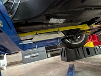
I put yellow tape along the spine so I could mark where the front mount would contact the spine.

PXL_20261023_194856286.jpg


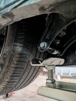
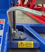
I loosened the rear mount on the BB main lift arm, so I could move that to where it would support the Spyder rear shock bottom bracket.

PXL_20261023_193758621.jpg


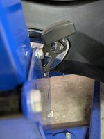
I positioned the BB to where it would clear the brake pedal, then pushed BB under the bike as far as it would go, which is just enough to have the mounts line up with the spine and shock mount (at this time the BB's adjustable bracket for the floorboard attachment was removed).

PXL_20261023_193952921.jpg


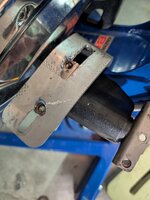
In this position, there was just enough clearance for the BB floorboard bracket to slip between the BB lifting arm and the Spyder's floorboard mount, but it was sitting at a weird angle relative to the floorboard mount; it would need to be reshaped. This I did with the bracket in a bench vice and some judicious pounding with a sledge hammer over the course of a couple of hours, until the desired shape was achieved.

I slipped the modified bracket into place and, because there was not space for the U-bolts, instead I reamed out and drilled the bracket to expose two of the four bolt holes that secure the floorboard normally.

PXL_20261023_191335204.jpg

I raised the BB lift arm to where it was just taking the Spyder's weight, then adjusted the floorboard bracket and secured it in place to the BB lift arm (17mm nut) and the floorboard mount holes.

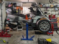
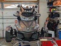
I finished lifting it all the way to the top (30") and took some pics. It's pretty stable and level. At this point, if I was going to leave it elevated to work on, I'd secure the rear mount to the shock mount with the U-bolts.

PXL_20261023_195121095.jpg - PXL_20261023_195152559.jpg

About those U-bolts; they don't fit the slots in the rear mount pillar bracket. Too wide. I had to squeeze them together in a vice and use a jack handle over the threaded arms of the U-bolts to straighten them back out. Now they work.

I can't believe I'm the only one who has had trouble making the BB work with an RT before...
 
Last edited:
Okay, it's done.
I put yellow tape along the spine so I could mark where the front mount would contact the spine.
View attachment 257507
I loosened the rear mount on the BB main lift arm, so I could move that to where it would support the Spyder rear shock bottom bracket.
View attachment 257508
I positioned the BB to where it would clear the brake pedal, then pushed BB under the bike as far as it would go, which is just enough to have the mounts line up with the spine and shock mount (at this time the BB's adjustable bracket for the floorboard attachment was removed).
View attachment 257509
In this position, there was just enough clearance for the BB floorboard bracket to slip between the BB lifting arm and the Spyder's floorboard mount, but it was sitting at a weird angle relative to the floorboard mount; it would need to be reshaped. This I did with the bracket in a bench vice and some judicious pounding with a sledge hammer over the course of a couple of hours, until the desired shape was achieved.

I slipped the modified bracket into place and, because there was not space for the U-bolts instead reamed out and drilled the bracket to expose two of the four bolt holes that secure the floorboard normally.
View attachment 257510
I raised the BB lift arm to where it was just taking the Spyder's weight, then adjusted the floorboard bracket and secured it in place to the BB lift arm (17mm nut) and the floorboard mount holes.

Finished lifting it all the way to the top (30") and took some pics. It's pretty stable and level. At this point, if I was going to leave it elevated to work on, I'd secure the rear mount to the shock mount with the U-bolts.
View attachment 257511 - View attachment 257512
About those U-bolts; they don't fit the slots in the rear mount pillar bracket. Too wide. Had to squeeze them together in a vice and use a jack handle over the threaded arms of the U-bolts to straighten them back out. Now they work.

I can't believe I'm the only one who has had trouble making the BB work with an RT before...
Way to stick with it. And yeah, it’s a steep learning curve. Now, do you remember what work you actually needed to perform on your RT?
 
  • Haha
Reactions: UtahPete
Okay, it's done.

I put yellow tape along the spine so I could mark where the front mount would contact the spine.

View attachment 257507


I loosened the rear mount on the BB main lift arm, so I could move that to where it would support the Spyder rear shock bottom bracket.

View attachment 257508


I positioned the BB to where it would clear the brake pedal, then pushed BB under the bike as far as it would go, which is just enough to have the mounts line up with the spine and shock mount (at this time the BB's adjustable bracket for the floorboard attachment was removed).

View attachment 257509


In this position, there was just enough clearance for the BB floorboard bracket to slip between the BB lifting arm and the Spyder's floorboard mount, but it was sitting at a weird angle relative to the floorboard mount; it would need to be reshaped. This I did with the bracket in a bench vice and some judicious pounding with a sledge hammer over the course of a couple of hours, until the desired shape was achieved.

I slipped the modified bracket into place and, because there was not space for the U-bolts, instead I reamed out and drilled the bracket to expose two of the four bolt holes that secure the floorboard normally.

View attachment 257510

I raised the BB lift arm to where it was just taking the Spyder's weight, then adjusted the floorboard bracket and secured it in place to the BB lift arm (17mm nut) and the floorboard mount holes.

I finished lifting it all the way to the top (30") and took some pics. It's pretty stable and level. At this point, if I was going to leave it elevated to work on, I'd secure the rear mount to the shock mount with the U-bolts.

View attachment 257511 - View attachment 257512

About those U-bolts; they don't fit the slots in the rear mount pillar bracket. Too wide. I h
ad to squeeze them together in a vice and use a jack handle over the threaded arms of the U-bolts to straighten them back out. Now they work.

I can't believe I'm the only one who has had trouble making the BB work with an RT before...

This is brilliant. I struggle to see the spine as well.
Will definitely try this next time.
 
  • Like
Reactions: UtahPete
... <snip> ...

I can't believe I'm the only one who has had trouble making the BB work with an RT before...

I don't think you are the only one who has encountered this sort of 'minor miss-match' in the bracketry Pete, but I do reckon that you're probably the only one who has spent so much time 'over-analyzing and over-thinking' it! 😉 😆

I'd guess that most -
  • just look at the lifting brackets and where they are meant to match up with the underside of the Spyder (regardless of the model);
  • see where they're 'close but not quite right'; sooo
  • they simply adjust the bracketry positioning to suit, probably without ever even reading the 'Instructions' at all!!
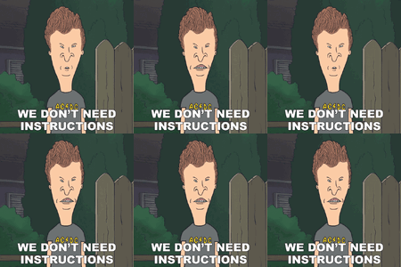
(Where's the right GIF when you need it?? :unsure: "Instructions! We don't need no stinking instructions!" 😣)

Welllll, it's not quite the one I had in mind, but here's one that'll work:

we-don't-need-instructions-butt-head-4078664420.gif

Just Sayin' ;)
 
Some follow on notes...

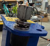
First, I learned the hard way to use caution when lowering the lift so it doesn't go past the point of no return. Busted the bearing at top of post and need to figure out a replacement from the aftermarket. Does anyone know how to do that?

PXL_20261023_212031807.jpg


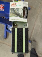
With the bike back on the ground, I thought I'd check the BB for clearance. Guess what? It fits just fine. I found if I angle it in toward the front of the Spyder first, the whole arm goes under the bike without having to lift the back end a little. Great.

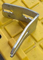
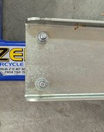
As you can see, the floorboard bracket got bent (deliberately) quite a bit. Amazing what a strong vise and sledgehammer can accomplish.

PXL_20261023_212934825.jpg - PXL_20261023_212659385.jpg

This pic shows where the rear mount now sits on the lifting arm

PXL_20261023_212732251.jpg

I'm glad that's over with. Next project...
 
  • Like
Reactions: Peter Aawen
Some follow on notes...

First, I learned the hard way to use caution when lowering the lift so it doesn't go past the point of no return. Busted the bearing at top of post and need to figure out a replacement from the aftermarket. Does anyone know how to do that?

View attachment 257515
Pete the bearing is not broke. I just received my new BB last week and put it together, unless the ball bearings came out. The bearing is three pieces. The loose top, loose bottom, and the bearings in a holder. Grease it up you should be good.
 
  • Like
Reactions: UtahPete
Pete the bearing is not broke. I just received my new BB last week and put it together, unless the ball bearings came out. The bearing is three pieces. The loose top, loose bottom, and the bearings in a holder. Grease it up you should be good.
That's good to know, thanks. I did lose some bearing balls, but that may be easier to rectify.
 
Some follow on notes...

First, I learned the hard way to use caution when lowering the lift so it doesn't go past the point of no return. Busted the bearing at top of post and need to figure out a replacement from the aftermarket. Does anyone know how to do that?

... <snip> ...

I'm glad that's over with. Next project...

Email Dave at EazyRider Big Blue. He should have what you need. He can also send you a new angle bracket if you need a backup.

[email protected]
 
  • Like
Reactions: UtahPete